Modern GPUs filter seamlessly across cube map faces. This feature is enabled automatically when using Direct3D 10 and 11 and in OpenGL when using the ARB_seamless_cube_map extension. However, it’s not exposed through Direct3D 9 and it’s just not available in any of the current generation consoles.
There are several solutions for this problem. Texture borders solve it elegantly, but are not available on all hardware, and only exposed through the OpenGL API (and proprietary APIs in some consoles).
When textures are static a common solution is to pre-process them in an attempt to eliminate the edge seams. In a short siggraph sketch, John Isidoro proposed averaging cube map edge texels across edges and obscuring the effect of the averaging by adjusting the intensity of the nearby texels using various methods. These methods are implemented in AMD’s CubeMapGen, whose source code is now publicly available online. While this seems like a good idea, a few minutes experimenting with CubeMapGen make it obvious that it does not always work very well!
Embedded Texture Borders
A very simple solution that even works for dynamic cube maps is to slightly increase the FOV of the perspective projection so that the edges of adjacent faces match up exactly. Ysaneya shows that in order to achieve that, the FOV needs to be tweaked as follows:
fov = 2.0 * atan(n / (n - 0.5))
where n is the resolution of the cube map.
What this is essentially doing is to scale down the face images by one texel and padding them with a border of texels that is shared between adjacent faces. Since the texels at the face edges are now identical the seams are gone.
In practice this is much trickier than it sounds. While the fragments at the adjacent face borders should sample the scene in the same direction, rasterization rules do not guarantee that in both cases the rasterized fragments will match.
However, if we take this idea to the realm of offline cube map generation, we can easily guarantee exact results. Cube maps are often used to store directional functions. Each texel has an associated uv coordinate within the cube map face, from which we derive a direction vector that is then used to sample our directional function. Examples of such functions include expensive BRDFs that we would like to precompute, or an environment map sampled using angular extent filtering.
Usually these uv coordinates are computed so that the resulting direction vectors point to the texel centers. For an integer texel coordinate x in the [0,n-1] range we map it to a floating point coordinate u in the [-1, 1] range as follows:
map_1(x) = (x + 0.5) * 2 / n - 1
We then obtain the corresponding direction vector as follows:
dir = normalize(faceVector + faceU * map_1(x) + faceV * map_1(y)
When doing that, the texels at the borders do not map to -1 and 1 exactly, but to:
map(0) = -1 + 1/n map(n-1) = 1 - 1/n
In our case we want the edges of each face to match up exactly to they result in the same direction vectors. That can be achieved with a function like this:
map_2(x) = 2 * x / (n - 1) - 1
If we use this map to sample our directional function, the resulting cube map is seamless, but the face images are scaled down uniformly. In the first case the slope of the map is:
map_1'(x) = 2 / n
but in the second case it is slightly different:
map_2'(x) = 2 / (n - 1)
This technique works very well at high resolutions. When n is sufficiently high, the change in slope between map_1 and map_2 becomes minimal. However, at low resolutions the stretching on the interior of the face can become noticeable.
A better solution is to stretch the image only in the proximity of the edges. That can be achieved warping the uv face coordinates with a cubic polynomial of this form:
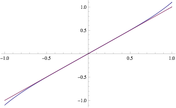
warp3(x) = ax^3 + x
We can compose this function with our original mapping. The result around the origin is close to a linear identity, but we can adjust a to stretch the function closer to the face edges. In our case we want the values at 1-1/n to produce 1 instead, so we can easily determine the value of a by solving:
warp3(1-1/n) = ax^3 + x = 1
which gives us:
a = n^2 / (n-1)^3
I implemented the linear stretch and cubic warping methods in NVTT and they often produce better results than the methods available in AMD’s CubeMapGen. However, I was not entirely satisfied. While this removed the zero-order discontinuity, it introduced a first-order discontinuity that in some cases was even more noticeable than the artifacts it was intended to remove.
The following images show how the warp edge fixup method eliminates the discontinuities, but sometimes still results in visible artifacts:
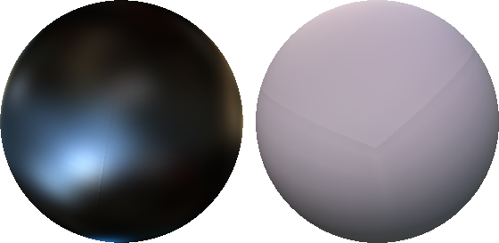
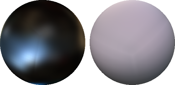
Any edge fixup method is going to force the slope of the color gradient across the edge to be zero, because it needs to duplicate the border texels. The eye seems to be very sensitive to this form of discontinuity and it’s questionable whether this is better than the original artifact. Maybe other warp functions would make the discontinuity less obvious, or maybe it could be smoothed like Isidoro’s method do. At the time I implemented this I thought the remaining artifacts did not deserve more attention and moved on to other tasks.
Modifed Texture Lookup
However, a few days ago Sebastien Lagarde integrated these methods in AMD’s CubeMapGen. See this post for more results and comparisons against other methods. That got me thinking again about this and then I realized that the only thing that needs to be done to avoid the seams is to modify the texture coordinates at runtime the same way we modify them during the offline cube map evaluation. At first I thought that would be impractical, because it would require projecting the texture coordinates onto the cube map faces, but turns out that the resulting math is very simple. In the case of the uniform stretch that I first suggested, the transform required at runtime is just a conditional per-component multiplication:
float3 fix_cube_lookup(float3 v) {
    float M = max(max(abs(v.x), abs(v.y)), abs(v.z));
    float scale = (cube_size - 1) / cube_size;
    if (abs(v.x) != M) v.x *= scale;
    if (abs(v.y) != M) v.y *= scale;
    if (abs(v.z) != M) v.z *= scale;
    return v;
}
One problem is that we need to know the size of the cube map face in advance, but every mipmap has a different size and we may not know what mipmap is going to be sampled in advance. So, this method only works when explicit LOD is used.
Another issue is that with trilinear filtering enabled, the hardware samples from two contiguous mipmap levels. Ideally we would have to use a different scale factor for each mipmap level. That could be achieved sampling them separately and combining the result manually, but in practice, using the same scale for both levels seems to produce fairly good results. We can easily find a scale factor that works well for fractional LODs as a function of the LOD value and the size of the top level mipmap:
float scale = 1 - exp2(lod) / cube_size;
if (abs(v.x) != M) v.x *= scale;
if (abs(v.y) != M) v.y *= scale;
if (abs(v.z) != M) v.z *= scale;
If you are using cube maps to store prefiltered environment maps, chances are you are computing the cube map LOD from the specular power using log2(specular_power). If that’s the case, the two transcendental instructions cancel out and the scale becomes a linear function of the specular power.
The images below show the results using the warp filtering method (these were chosen to highlight the artifacts of the warp method) compared with the new approach:
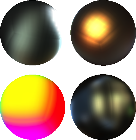
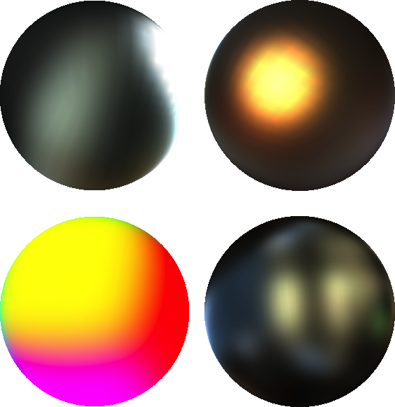
I’d like to thank Sebastien Lagarde for his valuable feedback while testing these ideas and for providing the nice images accompanying this article.